|
TileLogicTM
 |
|||||
|
|||||
|
© 2013, White Barn Tech
|
|
TileLogicTM
|
|||||||
|
|||||||
|
© 2013, White Barn Tech
|
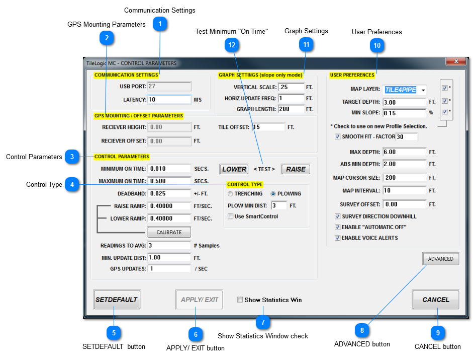
Communication Settings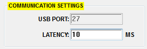
USB PORT: The port number of the usb port used with the MC122401 connection. Not user selectable, automatically configured.
LATENCY: The amount of milliseconds that TileLogic waits to receive a complete message from the MC122401 controller. Keep this value as low as possible, however, if CB Errors are persistent, increase this value.
|
GPS Mounting Parameters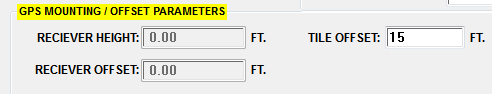
RECEIVER HEIGHT: The height from the machine's cutting surface and the GPS receiver.
RECEIVER OFFSET: The horizontal measurement from the GPS receiver center to the back of the machine where the tile exits.
TILE OFFSET: This is used as a reference for AUTO STOP. It is the distance from a reference point of the tile end, until it exits the machine completely. It is the discretion of the operator where this reference point is.
For an example, the reference point (the operator chooses) could be the entrance to a plow's feed roller to the end of the boot. The operator measures this to be 15 feet OF TILE. Set the TILE OFFSET = 15 (as shown). When installing a tile line, when the end of the tile is at the feed roller, depressing AUTO STOP will stop control automatically in 15 feet. This insures the best mapping, and that the tile end has cleared the machine.
|
Control Parameters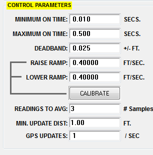 MINIMUM ON TIME: The minimum time that a hydraulic solenoid is pulsed to move the machine. MINIMUM ON TIME: The minimum time that a hydraulic solenoid is pulsed to move the machine.
MAXIMUM ON TIME: The maximum time that the hydraulic solenoid is allowed to be turned on.
DEADBAND: The range + or - from the target elevation where no machine control is attempted. Generally, this should be set to your GPS capabilities. If for example the GPS is only accurate to +/- .05 ft, set the deadband to this value.
RAISE RAMP: When the raise solenoid is on, the rate in feet / sec that the machine raises.
LOWER RAMP: When the lower solenoid is on, the rate in feet / sec that the machine lowers.
CALIBRATE BUTTON: Opens a calibration window, to initially set the raise and lower ramp values.
READINGS TO AVG: The number of GPS reading to average before determining a correction.
In "trencher mode", this is an absolute average.
In "plow mode", the number of readings are based on the speed (FPM) and GPS updates (see below), but never less than this setting.
MIN. UPDATE DIST: The distance the machine must travel before a correction can be made.
GPS UPDATES: The number of GPS updates / second. Setting this value to zero, will force TileLogic to automatically calculate this value when exited from the Control Parameters window.
|
User Preferences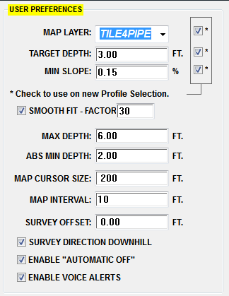
MAP LAYER: You may set a default map layer. If the box to the right is checked, this is automatically used when the profile is changed.
TARGET DEPTH: You may set a default target depth. If the box to the right is checked, this is automatically used when the profile is changed.
MIN SLOPE: You may set a default min. slope. If the box to the right is checked, this is automatically used when the profile is changed.
SMOOTH FIT - FACTOR - If checked, the factor (10 - 100) is used to smooth out transitions on a "SURVEY FIT" profile.
MAX DEPTH: - The maximum depth to attempt to stay above.
ABS MIN DEPTH: - The absolute minimum depth to stay below.
MAP CURSOR SIZE: - In machine control, the cross hair cursor size, shown on the machine control map window. This differs from the main map window, which shows the cursor width based on the map interval.
MAP INTERVAL: The map interval to use when in machine control. That is, how often to record a mapped point when in auto control. In feet.
SURVEY OFFSET: When performing an IP survey pass, this is typically done with the machines cutting surfaces in the fully raised position. Therefore this offset is the distance from the normally "benched position" to this raised position.
Example: The machine was benched at 0, 0, 100. At this location, the cutting surface (cutter wheel, plow tip) was set on the ground's surface. Prior to moving the machine, the operator raises the cutting surface to the fully raised position. For example, this elevation is 101.5. The survey offset is 101.5 - 100 = 1.5. Whenever you do an IP survey pass, raise the machine to it's fully raised position, and it's elevation is compensated for and referenced to the benched position.
SURVEY DIRECTION DOWNHILL: - When checked, you are performing IP survey passes from the end point to the outlet point. When unchecked, outlet point to end point.
ENABLE "AUTOMATIC OFF": When checked, enables the auto stop feature.
ENABLE VOICE ALERTS: - When checked, enables certain voice alerts. SAPI voices must be installed on your computer. Use the computer's Control Panel for settings and voices available.
|
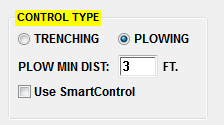
Graph Settings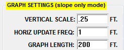
VERICAL SCALE: When profile selection is "NONE" and "SLOPE ONLY" profile mode, this is the vertical graph scale used.
HORIZ UPDATE FREQ: The horizontal distance to update the real time run graph. Used in all modes.
GRAPH LENGTH: When profile selection is "NONE" and "SLOPE ONLY" profile mode, this is the horizontal graph length to use.
|